Why Use Variable Frequency Motor Controllers?

Variable frequency motor controllers let a motor match its speed to the task instead of running at one fixed rate. In a pump room, that can mean easing the motor down when demand falls, rather than throttling flow with a valve. On a conveyor, it can mean a gentler start, less mechanical shock, and steadier product movement. The controller adjusts the electrical frequency supplied to the motor, and often its voltage as well. That control can improve process precision and reduce energy use in suitable applications. The result depends on the motor, load, operating profile, and installation.

Power-electronics scholar Bimal K. Bose’s work offers a useful principle: evaluate a motor drive as part of the complete system, not as an isolated device. That distinction matters. A variable frequency motor controller may deliver little benefit if a machine already runs near full load all day. It can also introduce heat, electrical noise, or added setup requirements that engineers must address. Not a magic fix. A sound evaluation starts with measured speed and load needs, then considers motor compatibility, protection, wiring, and maintenance. Even a simple pump can behave differently after speed control changes its operating point. The expected savings should be checked against real operating data, not a sales estimate alone. This guide examines why variable frequency motor controllers are used, where they perform well, and what deserves a closer look before selection. Some results are clear. Others need testing.
Why Use Variable Frequency Motor Controllers?

What a Variable-Frequency Motor Controller Does: Adjusting Frequency and Speed

A variable-frequency motor controller changes the electrical frequency supplied to an AC motor. Inside, a rectifier converts incoming AC to DC, and an inverter switches that DC into adjustable-frequency AC. Lowering frequency generally slows the motor; raising it increases speed within the motor’s rated limits. For an induction motor, actual speed remains slightly below synchronous speed because the rotor needs slip to produce torque. That distinction matters.

The controller usually adjusts voltage along with frequency, helping maintain magnetic flux as speed changes. For example, a conveyor carrying boxes may start gently at low frequency, then run faster once its load is moving. Acceleration and deceleration settings can reduce jolts, but overly short ramps may trigger overcurrent or stress a gearbox. At low speeds, a shaft-mounted fan may cool the motor less effectively, so duty cycle and temperature deserve attention. Check the motor nameplate, load behavior, and measured current during setup; frequency alone does not tell the whole story. The ratio is a guide, not a guarantee.

How VFDs Match Motor Speed to Pump and Fan Demand

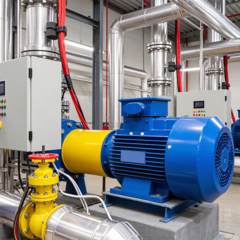
A variable frequency drive (VFD) adjusts the electrical frequency supplied to a motor, changing its speed as demand shifts. In a pump system, a pressure sensor can signal the drive to slow the motor when fewer taps are open. If demand rises, the drive increases speed to maintain the set pressure. That matters. Fans work similarly: a temperature or airflow signal can guide speed changes as rooms warm, cool, or empty.

Reducing speed can cut energy use because pumps and fans often need much less power at lower speeds. It can also soften starts and reduce abrupt pressure changes in pipes. Still, a VFD is not an automatic efficiency fix. Poor sensor placement, an unsuitable control setting, or a pump operating below its safe range can cause unstable flow. Motor cooling and system noise deserve attention, too. Real systems are messy.

Tips: Check pressure or airflow readings at the actual control point. Set minimum and maximum speeds with the equipment limits in mind, then observe the system under changing loads. A slight adjustment may help, but verify it over time.

DOE Estimates 20–50% Energy-Saving Potential in Variable-Load Systems

Why Use Variable Frequency Motor Controllers?

DOE Estimates 20–50% Energy-Saving Potential in Variable-Load Systems

A variable frequency motor controller adjusts motor speed to match changing demand. Instead of running a pump at full speed and restricting flow with a valve, the system can slow the motor. That difference matters during long hours of partial operation. A fan serving a lightly occupied building, for example, may not need full airflow all day.

The U.S. Department of Energy’s Improving Pumping System Performance: A Sourcebook for Industry, prepared with the Hydraulic Institute and Europump, reports potential energy savings of 20–50% from variable-speed control in suitable pumping applications. The range is broad for a reason. Savings depend on the load profile, motor and pump sizing, control settings, and operating hours. For centrifugal pumps and fans, reduced speed can sharply lower power demand, but the result should be measured at the system level.

Not magic. A controller on a system that already runs steadily near full load may offer little benefit. Poor setup can also create instability or maintenance issues. Before installation, log power and flow across a typical work cycle; a few readings during peak demand are not enough. The estimate is useful, but site data should decide.

Operational Benefits and Trade-Offs: Starting Current, Harmonics, and Heat

Why Use Variable Frequency Motor Controllers?
Operational Benefits and Trade-Offs: Starting Current, Harmonics, and Heat

A variable-frequency drive (VFD) controls motor speed by adjusting frequency and voltage. Its ramped start usually draws less current than direct-on-line starting, reducing brief voltage dips and mechanical shock. Results depend on motor size, load, acceleration time, and supply conditions. A heavily loaded conveyor still needs careful tuning. A gentle ramp may also extend startup longer than the process allows.

Harmonics are a key trade-off. The drive’s input electronics can distort current waveforms, especially across many drives or on a weak supply. This may increase transformer heating or affect sensitive equipment. Line reactors or harmonic filters can help, but selection should follow measurements and system design. Not a free gain. Heat also needs attention: at low speed, a motor’s shaft-mounted fan moves less air, while the drive adds switching losses. Check motor temperature and follow its speed range limits.

Tips: Record startup current and motor temperature under real load. If the motor runs slowly for long periods, consider independent cooling and verify harmonic levels at the supply.

Why Use Variable Frequency Motor Controllers?

Operational Benefits and Trade-Offs: Starting Current, Harmonics, and Heat

Typical starting-current ranges are shown as percentages of motor full-load current (FLA); actual values depend on the motor, load, and controller settings. Direct-on-line starting commonly draws about 600–800% of FLA, while a variable frequency drive (VFD) commonly limits starting current to roughly 100–150%. VFDs can introduce input-current harmonics, which may be reduced with suitable line reactors or filters. At low speeds, a motor’s shaft-mounted fan provides less cooling, so load limits, derating, or separate cooling may be needed.

Selecting a VFD: IEC 61800-3 EMC Requirements and Motor Compatibility

Why Use Variable Frequency Motor Controllers?

Selecting a VFD starts with its electromagnetic environment, not just its rated power. IEC 61800-3 classifies drive systems by where and how they are installed. C1 and C2 generally address first-environment use, while C3 and C4 cover more demanding industrial settings or specific installation conditions. The correct category depends on the complete installation, including the supply network and nearby equipment.

Check the drive’s EMC documentation against the site requirements. A shielded motor cable, proper cable glands, and short, low-impedance grounding connections can reduce conducted and radiated interference. Keep motor cables separate from sensor wiring where practical. A filter may help, but adding one without checking cable length and drive specifications can create new problems. The labels can mislead.

Motor compatibility matters just as much. Confirm that the motor’s voltage, current, insulation system, and operating range suit the VFD’s output. Fast switching pulses can stress older insulation, especially with long cables. At low speeds, a shaft-mounted fan may provide less cooling, so continuous heavy torque can cause overheating. Bearing currents may also need attention in larger installations. Check the motor and drive manuals together, then verify temperatures, noise, and fault behavior during commissioning. Specifications rarely tell the whole story. A setup that works on a test bench may behave differently beside sensitive instruments or across a long cable run.

Why Use Variable Frequency Motor Controllers? - Selecting a VFD: IEC 61800-3 EMC Requirements and Motor Compatibility

Selection dimension Requirement or technical fact Practical selection check
Why use a VFD? A variable frequency drive (VFD) controls an AC motor’s speed by varying the frequency and voltage supplied to it. It can support process control and reduce energy use in variable-torque applications such as many fans and pumps. Confirm the required speed range, load type, acceleration and deceleration needs, and whether the process can benefit from variable-speed operation.
IEC 61800-3 scope IEC 61800-3 addresses electromagnetic compatibility (EMC) requirements for adjustable-speed electrical power drive systems (PDS), including relevant emission and immunity considerations. Check the applicable standard edition, product documentation, installation instructions, and local regulatory requirements for the project.
First environment Generally includes residential premises and establishments directly connected to a low-voltage power supply network that also supplies residential buildings. Consider nearby sensitive equipment and the public low-voltage network when selecting the drive and EMC measures.
Second environment Generally includes locations other than those directly connected to the low-voltage network supplying residential buildings; industrial installations are common examples. Assess the site’s supply arrangement, other connected equipment, and the installation conditions specified for the drive.
Category C1 For PDS with rated voltage below 1,000 V intended for use in the first environment. Verify that the drive’s declared category and any required installation conditions match the intended location.
Category C2 For PDS with rated voltage below 1,000 V that are neither plug-in nor movable. For use in the first environment, installation and commissioning must be performed by a professional. Follow the manufacturer’s installation and commissioning instructions; additional EMC measures may be necessary for the site.
Category C3 For PDS with rated voltage below 1,000 V intended for use in the second environment. Do not assume a C3 drive is suitable for a first-environment installation without checking the specified conditions and mitigation requirements.
Category C4 Applies to PDS with rated voltage at or above 1,000 V, rated current at or above 400 A, or intended for use in complex systems in the second environment. Plan an EMC assessment for the installation; category C4 does not mean that the system can be installed without EMC engineering.
Motor cable and EMC Fast switching edges from a VFD can create conducted and radiated disturbances. Cable type, length, routing, shielding, and termination affect system performance. Use the cable and shield-termination method specified for the drive. Keep motor cables separate from sensitive signal wiring where practicable; there is no single maximum cable length that applies to every drive and motor.
EMC filters and installation Input filters, output filters, and other EMC measures must be selected for the specific drive, supply, motor cable, and installation. Filter use can affect leakage current and protective-device selection. Check filter compatibility, protective earthing, leakage-current information, and residual-current device requirements in the drive documentation.
Motor voltage and insulation A VFD’s PWM output can produce voltage stress at motor terminals. The stress depends on factors such as drive characteristics, cable length, and installation; motor suitability should not be judged by voltage rating alone. Check the motor manufacturer’s suitability for inverter operation and the drive’s guidance on cable length, output reactors, dv/dt filters, or sine-wave filters.
Motor and drive ratings The motor’s rated voltage, current, frequency, power, and connection must be compatible with the drive and supply. The drive must also be sized for the required load current and operating conditions. Compare motor nameplate data with the drive’s output ratings and application-specific overload capability; check the motor connection for the selected supply voltage.
Low-speed operation and cooling A standard motor’s shaft-mounted fan may provide less cooling at low speed. The allowable continuous torque at reduced speed depends on the motor design and operating conditions. Check the motor’s thermal limits and speed range. Consider separately powered ventilation or another motor cooling arrangement if required by the duty.
Bearing currents and grounding VFD operation can contribute to bearing-current risk in some motor and drive installations. Risk depends on the system design and operating conditions. Follow motor and drive guidance for bonding, grounding, cable layout, and any recommended bearing-current mitigation measures.
Commissioning verification EMC performance depends on the complete drive system and its installation, not solely on the drive unit in isolation. Record the selected EMC category, installation measures, motor and cable details, parameter settings, and any site verification required by the project.
Select Electrical Logo
Since 1988

Select Electrical Ltd. © Copyright 1988-2025