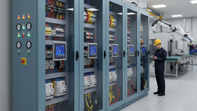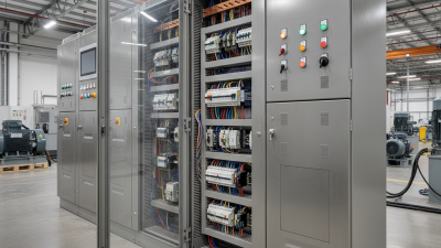
Choosing the best motor control solutions begins with the machine’s real operating conditions, not a product brochure. A conveyor moving heavy loads needs different control behavior from a high-speed cooling fan. Torque demand, starting frequency, speed range, heat, noise, and maintenance access all influence the decision.
Professor Thomas A. Lipo, a respected researcher in electric machines and drives, has emphasized, “The control of an electric machine cannot be separated from the machine itself.” This principle remains practical. A variable-frequency drive may reduce energy use, while servo control can deliver precise positioning. Sensorless control may lower hardware costs, but it can struggle at very low speeds. Small details matter.
The strongest motor control solutions combine suitable hardware, accurate tuning, and dependable protection. Engineers should examine motor ratings, feedback devices, braking needs, communication protocols, and fault records before choosing an architecture. IEC 61800-related requirements can also guide safer drive integration. Field experience often reveals what laboratory tests miss: a hot cabinet, a long cable, or vibration near the encoder.
No solution is perfect. That deserves attention.
A system may be efficient yet difficult to service. Another may offer excellent precision but exceed the project budget. Reliable selection therefore requires measurable comparisons, documented testing, and honest review after installation. The best answer is not always the newest technology. It is the solution that delivers stable performance, manageable risk, and practical value across the motor’s complete working life.

A strong motor control solution starts with the motor’s operating conditions, not only its price. NEMA MG 1 provides practical guidance for motor performance, construction, nameplate data, and efficiency. It also supports consistent selection across voltage, frequency, load, and service-factor conditions. That matters when a motor faces frequent starts, high ambient temperatures, or fluctuating loads.
IEC 60034-30-1 classifies line-operated AC motor efficiency through IE efficiency classes. The standard helps engineers compare tested motor performance under defined conditions. It does not, however, replace system analysis. A high-efficiency motor may save little energy if it runs far below its rated load. The International Energy Agency reports that electric motor systems consume roughly half of global electricity. Small efficiency gains can therefore produce substantial savings across industrial facilities.
A practical control review should compare NEMA MG 1 data with IEC efficiency classifications. Check rated current, duty, overload capacity, starting method, and actual load profile. Variable-speed applications require additional attention to cooling, harmonics, and minimum operating speed. A motor nameplate can still mislead when field conditions differ. That is an uncomfortable detail.
The U.S. Department of Energy’s motor-system guidance emphasizes that motor-driven equipment represents more than half of industrial electricity use. Engineers should measure energy before choosing replacements. Manufacturer test data, accredited laboratory methods, and documented commissioning records improve reliability. Standards guide decisions, but measurements expose the gaps.
What Are the Best Motor Control Solutions?
Choose Solutions for Systems Using 50–70% of Industrial Electricity (DOE)
Motor-driven systems consume roughly 50–70% of industrial electricity, according to the U.S. Department of Energy’s Motor Systems Market Assessment. That range changes the control question. A small efficiency gain can affect an entire plant’s energy profile. Variable frequency drives suit pumps, fans, and conveyors with changing loads. They reduce speed instead of wasting energy through throttling. For fixed-speed equipment, soft starters can limit inrush current and mechanical shock. Not always.
The best solution begins with the load profile, not the product label. Measure operating hours, starting frequency, speed demand, and process pressure. DOE guidance recommends evaluating the complete motor system, including transmission, controls, and driven equipment. A drive running continuously at low speed may still waste energy if poorly sized. Harmonic distortion, heat, and cable length also need attention. These details are easy to miss.
Industrial Energy Efficiency 2023 from the International Energy Agency stresses that digital monitoring and efficient electric systems can support major industrial savings. Practical systems may combine automatic speed control, current monitoring, overload protection, and planned maintenance. In a factory audit, abnormal vibration or rising amperage can reveal alignment problems before failure. Yet monitoring alone does not create efficiency. Data must guide a real adjustment. The honest answer is less perfect: the most advanced controller may underperform when sensors are badly placed or operators ignore alarms. Performance should be verified after installation, using measured electricity, production output, and power quality.
Choosing motor control equipment begins with the duty cycle, not the catalog. The International Energy Agency estimates that motor-driven systems consume about 53% of global electricity. Small efficiency gains can therefore produce measurable savings.
Contactors remain practical for simple on-off control. They are economical, fast, and easy to maintain. However, repeated starts can create current surges and mechanical stress. They also provide no meaningful speed regulation. Contactors generally fall under IEC 60947-4-1, rather than IEC 61800.
Soft starters reduce voltage during acceleration and deceleration. They suit pumps, fans, and conveyors with moderate starting demands. Reduced water hammer is a useful field benefit. Still, they cannot deliver continuous speed control. Their bypass arrangement also needs careful thermal and harmonic evaluation.
VFDs offer the broadest control range. Under IEC 61800, designers should review EMC, thermal limits, functional safety, and system efficiency. IEC 61800-3 addresses electromagnetic compatibility, while IEC 61800-9-2 supports efficiency assessment for drive systems. The U.S. Department of Energy reports that motor systems can represent more than 70% of industrial electricity use.
In commissioning work, a VFD often solves process problems beyond starting. Yet it can introduce bearing currents, cable reflections, and installation complexity. That trade-off is easy to underestimate. The best solution may be less advanced, not less engineered.
For fans and pumps, effective motor control often begins with speed adjustment, not maximum output. The affinity law offers a practical guide. Flow changes with speed. Pressure changes with speed squared. Power varies with speed cubed.
That reduction can lower heat, noise, and energy consumption. Small speed changes matter.
During commissioning, I compare motor speed, flow, pressure, and input power. A calibrated pressure sensor helps reveal whether the system performs as expected. However, the cube relationship is not perfect. Pipe friction, fluid viscosity, valve position, and minimum-flow requirements can affect actual results. I once trusted a simple calculation too much. The measured savings were lower because the valve remained partly closed.
Tips: Measure before adjusting. Check the pump’s minimum-flow requirement. Use gradual speed changes. Record readings at several operating points. Keep sensors maintained and verify unusual results. A lower speed is not always safer if cooling, lubrication, or process demand suffers.
Choosing a motor control solution requires more than checking torque and speed. In a real panel, heat, dust, cable length, and repeated starts affect performance. IEC 61800-5-2 helps engineers evaluate functional safety in adjustable-speed power drive systems. It addresses safety functions such as Safe Torque Off and Safe Stop 1. These functions must match the machine’s risk assessment, not merely appear in a datasheet. Good design begins with hazards, stopping times, and fault behavior.
Safety verification needs evidence. Engineers should review diagnostic coverage, response times, wiring architecture, and achievable SIL or PL levels. They should also test the complete chain, including sensors, drive logic, contactors, and mechanical brakes. A commissioning report should record test conditions and measured stopping distances. Labels can mislead. A drive may support a safety function, yet the installed system may not meet the required level. That gap is common.
Efficiency requires a separate lens. IE classes for motors are defined by IEC 60034-30-1, while drive losses need their own assessment. Compare motor efficiency at the actual load point, not only at rated power. Check standby consumption, switching frequency, cooling demand, and annual operating hours. A small efficiency gain matters when a pump runs continuously. Still, calculations can be imperfect. Load profiles are often estimated, and maintenance changes results. Measure current, temperature, and energy after commissioning. Real measurements matter.
| Motor Control Solution | Primary Control Capability | IEC 61800-5-2 Safety Relevance | Efficiency Verification | Typical Applications | Key Verification Points |
|---|---|---|---|---|---|
| Direct-on-Line Starter | Fixed-speed operation with full-voltage motor starting. | IEC 61800-5-2 generally does not apply because the system is not an adjustable-speed electrical power drive system. Emergency stopping and isolation normally require external safety measures. | Verify the motor efficiency class according to IEC 60034-30-1. A motor IE class does not describe the efficiency of the starter or the complete installation. | Simple pumps, fans, compressors, conveyors, and machines operating at one speed. | Check starting current, switching endurance, overload protection, motor IE class, and the safety circuit architecture. |
| Soft Starter | Controlled acceleration and deceleration with reduced mechanical shock and starting current; normally no continuous speed regulation. | IEC 61800-5-2 functions are not automatically provided. Any safety function must be explicitly specified, assessed, and integrated with the machine safety system. | Verify the motor IE class and the soft starter's operating losses, bypass arrangement, and thermal requirements. IE classes apply to motors, not soft starters. | Large pumps, fans, compressors, and conveyors where smooth starting is required but variable speed is unnecessary. | Review bypass losses, number of starts per hour, ramp settings, overload capacity, and external emergency-stop provisions. |
| Standard Variable-Frequency Drive | Continuous speed, torque, acceleration, braking, and energy control for AC motors. | The drive may include a safety function such as Safe Torque Off (STO), but the function must be declared and supported by safety data. A standard control input is not equivalent to a safety-rated STO input. | Assess both the motor IE class under IEC 60034-30-1 and the complete power drive system efficiency class under IEC 61800-9-2, where applicable. | Variable-speed pumps, fans, conveyors, mixers, machine tools, and HVAC systems. | Check motor-drive compatibility, operating point, switching frequency, standby consumption, regenerative losses, harmonics, and declared efficiency data. |
| Safety-Capable Variable-Frequency Drive | Variable-speed control combined with integrated safety functions for controlled stopping and restricted operation. | May support STO and, depending on the design, functions such as Safe Stop 1 (SS1), Safely-Limited Speed (SLS), Safe Operating Stop (SOS), or Safe Brake Control (SBC). The achieved SIL or PL depends on the complete safety-related control system and validation. | Verify motor IE class separately and evaluate the complete drive system using the efficiency concepts and test methods of IEC 61800-9-2. | Robotics, automated production lines, elevators, packaging equipment, presses, and machinery with frequent access or hazardous motion. | Request the safety manual, PFHD or equivalent safety data, achieved SIL/PL, proof-test assumptions, fault exclusions, wiring requirements, and validation records. |
| Servo Drive and Motor System | Closed-loop position, speed, and torque control with high dynamic response and precise synchronization. | Safety functions may be integrated, including STO, SS1, SLS, or safe motion monitoring. Safety performance must be evaluated for the drive, motor feedback, controller, wiring, and application software as a complete system. | Verify the motor's applicable IE classification and assess drive-system losses across the actual duty cycle, including standby, acceleration, deceleration, and holding periods. | Robotic axes, CNC equipment, printing, filling, labeling, semiconductor equipment, and high-speed positioning systems. | Check feedback integrity, braking energy, peak and continuous torque, thermal duty, safety response time, and motion-profile energy consumption. |
| Regenerative or Four-Quadrant Drive System | Motoring and braking in both rotational directions, with the ability to return braking energy to a DC bus or supply when designed for regeneration. | Safety functions such as STO or safe speed monitoring may be included, but energy regeneration does not itself provide a safety function under IEC 61800-5-2. | Evaluate total-system efficiency and regenerated energy over the duty cycle. Motor IE class alone cannot represent the efficiency of a regenerative installation. | Cranes, hoists, test benches, elevators, centrifuges, winding machines, and high-inertia equipment. | Check regeneration efficiency, braking resistor sizing, DC-bus protection, grid interaction, harmonic performance, and safe stopping under power-loss conditions. |
| Efficiency Class Reference | |||||
| IE1–IE5 Motor Classes | IEC 60034-30-1 defines international efficiency classes for line-operated AC motors. IE1 is Standard Efficiency, IE2 is High Efficiency, IE3 is Premium Efficiency, and IE4 is Super Premium Efficiency. IE5 is used for Ultra-Premium Efficiency where the applicable motor technology and edition of the standard support it. | The minimum efficiency value is not one universal percentage; it varies with rated output, number of poles, frequency, and motor operating conditions. | Confirm the exact rated efficiency on the motor nameplate or technical documentation and compare it at the intended load point. | ||
| IES Classes for Power Drive Systems | IEC 61800-9-2 addresses the efficiency classification and determination of losses for complete power drive systems, including the converter and motor combination. | Use IES data rather than a motor-only IE value when comparing variable-speed drive packages. Results depend on the operating point and load profile. | Request loss or efficiency data at the required speed and torque points, not only at nominal motor conditions. | ||
| Important selection note: IEC 61800-5-2 addresses functional safety for adjustable-speed electrical power drive systems, while motor IE classes are primarily covered by IEC 60034-30-1 and complete power drive system efficiency is addressed by IEC 61800-9-2. A safety claim or efficiency class should be accepted only when supported by applicable technical documentation, operating conditions, and system-level verification. | |||||