
What Is CNC Turning Machining and How Does It Work?

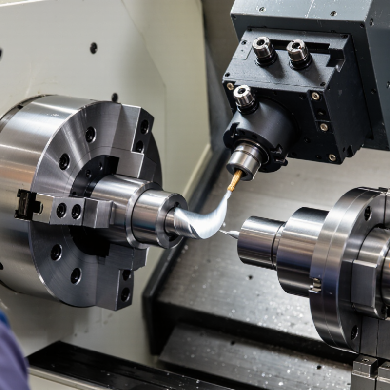
Cnc Turning Machining is a subtractive manufacturing process used to create precise cylindrical components. It rotates a workpiece while a cutting tool removes controlled amounts of material. The tool follows programmed paths, shaping diameters, shoulders, grooves, threads, and internal features. Simple in principle. Highly controlled in practice.

A CNC turning center usually includes a spindle, chuck, turret, cutting tools, control system, and measurement equipment. The spindle holds the material firmly and controls its rotational speed. The turret positions each tool with repeatable accuracy. Feed rate, cutting depth, tool geometry, and material hardness all affect the finished surface. Experienced machinists watch chip color, vibration, and sound during production. These details often reveal problems before inspection confirms them.

This article explains how the turning cycle works, from digital design and tool selection to setup, machining, and quality checks. It also discusses common materials, typical applications, process benefits, and practical limitations. For example, aluminum may cut smoothly, while stainless steel can generate heat and harden under poor conditions. That difference matters. Programming alone does not guarantee a good part. Tool wear, workholding errors, thermal expansion, and incorrect measurements can still reduce accuracy. A reliable process therefore combines proven machine settings, skilled supervision, documented inspections, and suitable tolerances. Some results remain imperfect, especially during early setup. Recognizing and correcting those imperfections is part of professional machining, not a failure of the technology.
What Is CNC Turning Machining and How Does It Work?

What Is CNC Turning Machining?

CNC turning machining is a subtractive manufacturing process for producing round or cylindrical parts. CNC means computer numerical control. A programmed system directs the machine’s movements with precise, repeatable instructions. During operation, the workpiece rotates inside a chuck while a cutting tool removes material from its outer surface. In simple terms.

The process usually begins with a digital drawing and a machining program. An operator selects suitable stock, secures it, and checks the tool position carefully. The machine then controls spindle speed, feed rate, and cutting depth. It can create diameters, grooves, tapers, threads, and smooth end faces. Coolant may reduce heat and carry chips away from the cutting zone. Aluminum, steel, brass, plastics, and other materials can be turned with suitable tools and settings.

Accuracy depends on more than software. Tool wear, workholding pressure, material variation, and temperature can affect the final part. From practical machining experience, a clean setup often matters as much as a clever program. A loose chuck can leave marks or cause dimensional errors. That mistake is easy to underestimate. Operators commonly measure critical diameters with micrometers during production, not only after the batch ends. CNC turning is highly consistent, but it is not automatically perfect. Careful inspection and occasional program review remain necessary.

How a CNC Turning Machine Operates

CNC turning machining shapes round components by removing material from a rotating workpiece. A computer-controlled lathe guides cutting tools along programmed paths. The machine usually handles shafts, bushings, pins, and other cylindrical parts. An operator begins with a digital drawing and converts its dimensions into machine instructions. The workpiece is clamped inside a chuck and aligned with the spindle axis. This alignment must be accurate. Even a small offset can create uneven diameters or poor surface finishes.

During operation, the spindle rotates at a selected speed while the tool moves across the material. Feed rate, cutting depth, and tool geometry affect heat, accuracy, and tool life. Coolant may reduce friction and carry chips away from the cutting zone. The control system follows each programmed movement, but it does not replace careful setup. In my experience, the first test cut is rarely perfect. A measured diameter may differ slightly from the drawing. Operators check the part with micrometers, calipers, or gauges, then adjust tool offsets when necessary. Sharp tools help. Worn tools can leave grooves, burrs, or unwanted dimensions. Material hardness also changes the cutting response, so proven settings may still need practical adjustment.

Key Components of a CNC Turning System

A CNC turning system combines several precise components around a rotating workpiece. The spindle motor supplies rotational force, while the chuck or collet holds the material securely. Even slight clamping errors can create taper, vibration, or poor surface finish.

The CNC controller is the system’s decision center. It interprets programmed coordinates and sends commands to servo drives. These drives move the cutting tool along the X and Z axes. The turret stores multiple tools and indexes the correct insert within seconds. A tailstock supports long shafts and reduces deflection. Without it, a slender workpiece may bend during cutting. That assumption is often wrong.

Coolant lines control heat and carry chips away from the cutting zone. Sensors monitor spindle load, position, temperature, and tool condition. Their feedback helps operators detect abnormal cutting before scrap increases. The U.S. Department of Energy reports that motor-driven systems can account for about 69% of manufacturing electricity use. Efficient spindle and axis drives therefore affect both accuracy and operating cost. Grand View Research estimated the global CNC machine market at USD 83.99 billion in 2023, with a projected 9.5% annual growth through 2030. More machines also mean more maintenance decisions. In shop-floor practice, a clean cut does not always prove a healthy system. A worn chuck jaw or misaligned turret can remain unnoticed until final inspection.

Step-by-Step CNC Turning Process

CNC turning machining shapes rotating workpieces with a fixed cutting tool. According to Grand View Research’s 2024 CNC machine market report, the global market was valued at about $83.9 billion in 2023. This growth reflects demand for repeatable, digitally controlled production. The process begins with a technical drawing, material check, and machining plan. An operator selects the chuck, inserts, spindle speed, feed rate, and cutting depth. Small errors here can damage the workpiece later.

The machine clamps the bar or blank, then checks runout with a dial indicator. Accurate alignment matters. The controller loads the programmed toolpath, often using standard G-code. The spindle rotates the material while the tool removes stock during roughing passes. Coolant may reduce heat and carry chips away. Finishing passes then create the required diameter, shoulder, groove, or thread. ISO 230-1 testing guidance emphasizes machine accuracy and repeatability, but real workshops still face vibration, tool wear, and thermal drift. The first pass is rarely perfect.

Tips: Measure the raw diameter before cutting. Confirm tool offset values at the control panel. Use a slower finishing feed when surface quality matters. Inspect critical features with a micrometer, not only the machine display. A practical improvement is recording insert wear after each batch. This habit reveals patterns, although it can feel excessive during short runs. Check burrs by touch carefully, and keep hands away from moving parts.

What Is CNC Turning Machining and How Does It Work? - Step-by-Step CNC Turning Process

Step Process Stage What Happens Typical Machine or Tool Action Typical Parameters Main Output or Quality Check
1 Review the CAD Design The part drawing is examined for dimensions, tolerances, threads, grooves, radii, chamfers, and surface-finish requirements. The machinist identifies turning features and confirms which surfaces can be produced by rotating the workpiece. Dimensional tolerances commonly range from approximately ±0.01 to ±0.10 mm, depending on the design and process. A complete process plan and an approved engineering drawing.
2 Select the Raw Material A cylindrical bar, tube, or prepared blank is selected with sufficient allowance for machining. The material is checked for diameter, length, grade, straightness, and visible defects before loading. Common materials include steel, stainless steel, aluminum, brass, copper, titanium, and engineering plastics. Correct material certification and an appropriate stock allowance.
3 Prepare the CNC Program The design is converted into toolpaths and machine instructions, usually using computer-aided manufacturing software. The program defines spindle speed, feed rate, cutting depth, tool changes, coolant commands, and work offsets. Programming may use metric or imperial units; cutting values depend on material, tooling, and machine capability. A verified numerical-control program with no toolpath collisions.
4 Set Up the Workholding The raw stock is secured so that it rotates concentrically and remains stable during cutting. A three-jaw chuck, collet, soft jaws, or other suitable fixture holds the workpiece. Runout is checked with a dial indicator; the acceptable value depends on the required part accuracy. Secure clamping, correct protrusion, and controlled radial runout.
5 Install and Measure Cutting Tools Turning inserts, drills, boring bars, grooving tools, or threading tools are installed in the turret. Tool geometry, insert condition, tool number, length offset, and radius compensation are entered or measured. Insert geometry and grade are selected according to material, cutting load, and required surface finish. Correct tool offsets and sharp, undamaged cutting edges.
6 Set Work Coordinate and Dry Run The machine establishes the workpiece zero point and checks the programmed motion before cutting material. The operator touches off tools, sets the work offset, verifies clearance, and performs a simulation or single-block run. Clearance is verified at rapid-traverse positions and near the chuck, jaws, tailstock, and finished surfaces. Confirmed origin, safe tool motion, and correct machining sequence.
7 Face the Workpiece Material is removed from the end of the stock to create a flat reference surface. A facing tool moves radially across the rotating end face. Feed and speed are selected according to workpiece diameter, material, insert geometry, and machine limits. Flat end face and a reliable axial reference for subsequent operations.
8 Perform Rough Turning Large amounts of material are removed quickly to approach the required external profile. The tool travels along the workpiece axis while the spindle rotates the stock. A machining allowance is intentionally left for finishing; cutting depth depends on material and machine rigidity. Efficient stock removal without excessive vibration, heat, or tool wear.
9 Machine Special Features Additional operations create holes, bores, grooves, tapers, radii, chamfers, or external and internal threads. Live tooling, drills, boring bars, grooving tools, and threading tools may be used, depending on the lathe configuration. Thread pitch, bore diameter, groove width, and taper angle are programmed from the drawing. Accurate functional features that match the specified geometry.
10 Perform Finish Turning A smaller final cut removes the remaining allowance and produces the required dimensions and surface quality. The finishing tool follows the final contour at a controlled feed rate. Surface roughness may be specified as Ra; achievable values depend on tool nose radius, feed, material, and machine stability. Final profile, diameter, length, and surface finish.
11 Apply Coolant and Manage Chips Cutting fluid may reduce heat, improve tool life, flush chips, and support consistent surface quality. Flood coolant, through-tool coolant, air, or dry machining is selected according to the material and operation. Coolant concentration and flow must follow the process requirements and safety procedures. Controlled cutting temperature, manageable chips, and reduced risk of chip recutting.
12 Inspect the Finished Part The completed part is checked against the drawing and process specifications. Calipers, micrometers, gauges, thread gauges, height gauges, or coordinate-measuring equipment may be used. Inspection frequency and instrument resolution are selected according to tolerance and quality requirements. Accepted dimensions, surface finish, threads, burr condition, and overall conformity.
13 Deburr and Complete the Part Sharp edges and machining residues are removed, and any specified cleaning or protective treatment is completed. Manual deburring, brushing, washing, polishing, or other approved finishing methods may be applied. Edge-break size and final treatment are controlled by the technical drawing or inspection standard. Clean, safe-to-handle parts ready for assembly, packaging, or further processing.
Note: Actual cutting speeds, feed rates, depths of cut, tolerances, and surface-finish results vary with material grade, workpiece size, tool geometry, machine rigidity, coolant strategy, and production requirements.

Common Applications and Material Choices

What Is CNC Turning Machining and How Does It Work?

CNC turning machining shapes a rotating workpiece with a controlled cutting tool. The chuck holds the material firmly, while the spindle controls its speed. A programmed tool path removes material from the outside, inside, or face of the part. Threads, grooves, tapers, and precise diameters can be produced in one setup. Operators still inspect tool wear, surface finish, and dimensions during production. Automation reduces variation, but it does not remove the need for judgment.

Common applications include shafts, bushings, pins, threaded fittings, rollers, and custom spacers. Aluminum suits lightweight housings and fast production. Carbon steel provides strength for shafts and mechanical supports. Stainless steel resists corrosion, but it can generate heat and harden during cutting. Brass machines smoothly for fittings and decorative components. Engineering plastics work well for low-load guides and insulating parts. Titanium is strong and light, although it requires careful speed, feed, and cooling control. A drawing may suggest one material, yet the actual cutting behavior can challenge that choice.

Tips: Match the material to load, temperature, corrosion, and finish requirements. Confirm bar diameter before programming. Use sharp tooling and suitable coolant when heat builds. Check the first part against the drawing, especially thread depth and shoulder length. Small errors matter. A perfect material choice on paper may still machine poorly, so testing a sample remains valuable.

Select Electrical Logo
Since 1988

Select Electrical Ltd. © Copyright 1988-2025