Choosing among the top electric motor VFD types starts with a practical question: what must the motor do? A variable frequency drive changes motor supply frequency and voltage to regulate speed, but the best choice depends on the load, operating range, and control demands. A pump running steadily has different needs from a conveyor that starts under load. Small details matter.
This guide compares common drive designs and control methods without treating them as interchangeable. Voltage-source inverter drives are widely used, while current-source designs suit particular power and application requirements. Within these broad categories, pulse-width modulation and control approaches such as volts-per-hertz, sensorless vector, and closed-loop vector affect performance in different ways. They are related, but they describe different aspects of a drive.
Expect practical trade-offs, not a universal winner. A basic V/f setup can be suitable for straightforward fan or pump duty; demanding low-speed torque may call for vector control. Check the motor nameplate, drive current rating, overload needs, enclosure, cooling, and braking requirements before comparing models. Cable length, electrical noise, and installation conditions can also influence selection. Small oversights can become costly.
The comparisons ahead explain where each type fits, what it does well, and what to verify with a qualified supplier or engineer. Manufacturer documentation should guide final sizing and installation. No shortlist replaces that step. A careful match usually matters more than the most advanced feature list.
A variable frequency drive (VFD) adjusts the electrical frequency supplied to a motor, controlling its speed to match the work required. It typically converts incoming AC power to DC, then creates a variable-frequency AC output. That changes speed, not merely voltage. In a pump room, for example, a VFD can slow a motor when demand falls instead of forcing a valve to restrict flow. The International Energy Agency’s 2011 report, Energy-Efficiency Policy Opportunities for Electric Motor-Driven Systems, estimates these systems use about 45% of global electricity. Small control changes can matter at scale.
The U.S. Department of Energy’s pumping-system guidance describes the affinity-law relationship: for an ideal centrifugal pump, power varies approximately with the cube of speed. At 80% speed, that implies roughly 51% of full-speed power demand. Real systems differ. Pipe friction, pump condition, and control settings all affect results, so the estimate is not a guaranteed saving. A VFD can also provide soft starting, reducing abrupt mechanical stress on shafts and couplings. But the drive must be matched to the motor and load. Poor settings can cause overheating or unstable operation. The details are easy to miss. A measured baseline and post-installation readings make the claimed benefit more credible.
A VFD’s power-conversion design describes how it changes incoming electrical power into variable-frequency output for a motor. The most common arrangement is a voltage-source inverter (VSI). It rectifies AC into DC, smooths it through a capacitor-based DC link, then switches that energy into adjustable-frequency AC. Many general-purpose drives use this design. It suits pumps, fans, and conveyor motors, but its input harmonics and braking needs still require attention.
A current-source inverter (CSI) uses a large DC-link inductor to maintain current, rather than relying on a capacitor to hold voltage. This makes its behavior different during faults and regeneration, though the complete drive topology determines those capabilities. Direct AC-to-AC designs include cycloconverters and matrix converters. Cycloconverters are commonly associated with very large, low-speed applications; matrix converters convert power without a conventional DC link. Their control and filtering can be more demanding.
The topology is only part of the selection. Check the motor’s voltage, load profile, required speed range, braking duty, and installation conditions. A drive that runs a lightly loaded fan may not suit a loaded hoist. Details matter. In practice, specifications can omit useful context, so verify the manufacturer’s technical data and consult a qualified drive engineer when requirements are uncertain. No single conversion design is best for every motor or site.
Power-conversion designs compared by the number of conversion stages.
Voltage-source and current-source inverter drives convert AC to DC and then back to AC. Cycloconverters and matrix converters perform direct AC-to-AC conversion. The chart counts conversion stages, not components or relative performance.
An electric motor VFD can use a voltage-source inverter (VSI) or a current-source inverter (CSI). The key difference is what the drive controls after converting incoming power to DC. A VSI maintains a relatively stable DC voltage, often with capacitors in its DC link. Switching devices shape that voltage into variable-frequency output for the motor. This is a familiar approach in many general-purpose drives.
A CSI uses a large inductor in the DC link to keep current relatively steady. The inverter switches that current among motor phases to regulate operation. This design can suit high-power applications and support regenerative energy flow, depending on the drive system. It also brings trade-offs: the inductor takes space, and motor-side behavior needs careful coordination. Not a small detail.
For a plant engineer, the choice often starts with the load, power level, and braking needs—not just the motor nameplate. A VSI may be simpler across varied machines. A CSI can fit where current control and regeneration matter. Yet installation conditions, protection, and maintenance skills can change the answer. I would check the actual duty cycle before treating either topology as the default. The distinction sounds tidy on paper. Real systems are less tidy.
| Comparison Dimension | Voltage-Source Inverter (VSI) VFD | Current-Source Inverter (CSI) VFD |
|---|---|---|
| DC-link component | Typically uses a large DC-link capacitor to maintain a relatively stable DC-bus voltage. | Typically uses a large DC-link inductor to maintain a relatively stable DC-link current. |
| Inverter output | Switches the DC-bus voltage to produce a variable-frequency, variable-voltage motor supply. PWM is commonly used. | Controls the current delivered to the motor; the motor-terminal voltage varies with the load and operating conditions. |
| Common power devices | Modern designs commonly use IGBTs; other devices may be used depending on the drive’s voltage and power rating. | May use thyristors or controllable semiconductor switches such as GTOs, IGCTs, or IGBTs, depending on the design and rating. |
| Typical applications | Widely used for pumps, fans, conveyors, compressors, machine tools, and other low- and medium-voltage motor applications. | Used in some medium- and high-power applications, including large industrial drives where its current-source topology is suitable. |
| Motor compatibility | Commonly applied to standard induction motors and, with suitable drive controls, synchronous motors. | Requires a drive-and-motor combination designed for CSI operation; output capacitors and motor characteristics must be considered. |
| Regenerative operation | Regeneration to the supply generally requires a regenerative front end. A braking resistor can dissipate energy where regeneration is not required. | Regeneration is possible with an appropriately designed front end and control system; it is not automatic for every CSI drive. |
| Output waveform considerations | PWM produces a switched voltage waveform. Motor insulation, cable length, and voltage reflections may need attention; output reactors or filters can be used when appropriate. | The inverter produces controlled current pulses. Output capacitors are commonly used as part of the circuit design, and the motor must be suitable for the resulting waveform. |
| Typical strengths | Broad availability, flexible control, and suitability for a wide range of applications and power ratings. | Can be advantageous in certain high-power drive designs and can provide a current-limited output characteristic. |
| Selection factors | Consider motor type, supply voltage, power rating, speed range, braking or regeneration needs, and cable conditions. | Consider power rating, motor compatibility, required regeneration, system design, and the availability of qualified service support. |
Note: Features and performance vary by drive design, rating, control method, and application. Confirm motor and drive compatibility with the equipment specifications.
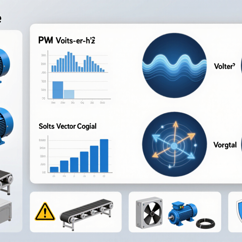
PWM, six-step, and matrix converter drives create variable-speed motor power in different ways. Their circuit choices affect current quality, efficiency, and system complexity.
A PWM VFD switches its DC bus rapidly, shaping pulses into a controllable AC waveform. The motor’s inductance smooths those pulses, helping produce steady torque at low speeds. Engineers can adjust switching frequency, but higher frequencies may increase heat in the drive and motor. Long motor cables can also make voltage reflections worth checking. The details matter.
A six-step VFD changes output voltage through six switching states per electrical cycle. Its simpler switching pattern can suit robust, high-power applications. However, the stepped waveform may cause more harmonic current, audible motor noise, and torque ripple than PWM. A larger motor may tolerate this well; a sensitive load may not. That distinction is easy to overlook.
A matrix converter changes AC directly into variable-frequency AC without a large DC-link capacitor. This can support compact designs and bidirectional power flow, but control and input filtering are more demanding. Its available output voltage is also limited relative to the input. On paper, the architecture looks elegant. In a real installation, protection, load behavior, and maintenance access can change the decision.
Selecting a VFD starts with the motor and the work it must do, not horsepower alone. Check the motor nameplate for voltage, current, frequency, and whether it is an induction or permanent-magnet motor. Then map the load: a centrifugal pump usually needs less torque at low speed, while a loaded conveyor may need strong starting torque. That detail matters.
For steady pump or fan speed control, a basic V/f control drive may be sufficient. Applications that need better low-speed torque or faster response often benefit from vector control; precise speed regulation may require encoder feedback. Not always. Confirm the drive supports the motor type and the required control method. Size it by motor current and overload demand, not just its kilowatt rating. A conveyor that starts several times an hour can need a different overload rating from one that runs continuously.
Finally, consider the installation. A dusty cabinet, high ambient temperature, long motor cable, or frequent speed changes can affect drive selection and setup. Check enclosure protection, cooling, cable guidance, and any required output filtering. A neat sizing spreadsheet can still miss real operating conditions. Measure the actual load where possible, and leave room to revisit assumptions after commissioning.