What Is a 3 Phase Electric Motor and How Does It Work?

A 3 phase electric motor converts electrical energy into continuous mechanical rotation. Unlike a single-phase motor, it receives three alternating currents, separated by 120 electrical degrees. These currents create a rotating magnetic field inside the stator. The field pulls the rotor around the air gap, producing torque for pumps, compressors, conveyors, and machine tools.

The principle sounds simple. Real systems are less forgiving. Slight voltage imbalance can increase winding temperature and shorten insulation life. Poor alignment can produce vibration, noise, and premature bearing failure. Engineers therefore examine voltage, current, load, duty cycle, cooling, and the installation environment before selecting a motor. A warm motor frame, a humming bearing, or an unexpected current rise can reveal problems that calculations miss.

The scale of this equipment matters. The International Energy Agency’s Energy Efficiency Market Report 2016 identified motor-driven systems as responsible for nearly half of global electricity consumption. The U.S. Department of Energy has also reported that industrial motor systems consume a major share of factory electricity, commonly estimated near 70% in industrial facilities. These figures explain why efficiency classes, variable-frequency drives, and correct sizing deserve attention. IEC 60034 standards provide widely used requirements for rotating electrical machines, including performance and testing considerations.

This guide explains how a 3 phase electric motor works, from the stator’s magnetic field to rotor torque and shaft output. It also considers efficiency, starting current, speed control, and maintenance. One warning remains important: nameplate data alone is not enough. Actual performance depends on the entire driven system.
What Is a 3 Phase Electric Motor and How Does It Work?

Definition and Core Components of a Three-Phase Electric Motor

A three-phase electric motor converts electrical energy into mechanical rotation. It uses three alternating currents, separated by 120 electrical degrees, to create a rotating magnetic field. This arrangement produces smoother torque than many single-phase designs. It also supports efficient operation in pumps, compressors, conveyors, and industrial fans.

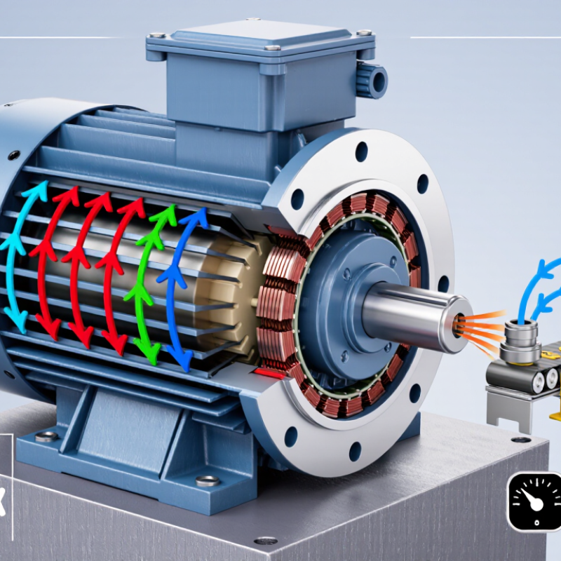
The stator forms the stationary outer section. It contains a laminated steel core and three insulated winding sets placed in precise slots. Laminations reduce circulating electrical losses, while the windings receive the three-phase supply.

The rotor sits inside the stator with a narrow air gap. In an induction motor, current develops in the rotor conductors through electromagnetic induction. The rotor then follows the rotating field, but it must turn slightly slower. That difference is called slip.

Key mechanical components include the shaft, bearings, cooling fan, and protective enclosure. The shaft transfers torque to the driven machine. Bearings maintain alignment and limit friction. The enclosure helps control dust, moisture, and accidental contact, although its protection depends on the installation environment.

A terminal box connects the incoming conductors to the windings. During practical inspection, unusual vibration, heat, or humming can reveal poor alignment or electrical imbalance. A motor may still run under these conditions. That does not mean it is healthy. Designers also need to consider starting current, load demand, insulation condition, and ventilation before selecting or servicing a three-phase motor.

How Three-Phase Alternating Current Produces a Rotating Magnetic Field

A three-phase electric motor converts electrical energy into mechanical rotation. Its key action begins with three alternating currents inside the stator. These currents share the same frequency and voltage pattern, but their peaks arrive 120 electrical degrees apart. That timing matters. Copper windings are distributed around the stator, so each current creates a changing magnetic field in a different position. The three fields combine into one continuous rotating magnetic field.

The field does not switch abruptly from one coil to another. It travels smoothly around the stator, like an invisible carousel. Its synchronous speed depends on supply frequency and pole count: speed equals 120 times frequency divided by the number of poles. A four-pole motor supplied at 50 hertz therefore produces a 1,500-rpm rotating field. The rotor usually turns slightly slower. This difference, called slip, allows electromagnetic induction to produce rotor current and torque.

In a workshop, unusual noise or excess heat can reveal phase imbalance, loose connections, or bearing problems. A technician checks voltage between phases and confirms the correct phase sequence before operation. Swapping two supply lines reverses the rotating field, but testing must follow approved electrical procedures. The textbook picture is clean; real motors are less perfect. Magnetic losses, friction, and small manufacturing differences reduce efficiency. That imperfection is easy to overlook when the motor appears to run normally.

What Is a 3 Phase Electric Motor and How Does It Work? - How Three-Phase Alternating Current Produces a Rotating Magnetic Field

Technical Dimension Typical Value or Relationship Explanation
Definition Electromechanical energy converter A three-phase electric motor converts electrical energy from a three-phase alternating-current supply into mechanical rotational energy.
Number of AC phases 3 phases The three stator windings are electrically displaced by 120 degrees from one another, creating three sinusoidal currents with the same frequency and ideally equal magnitude.
Phase sequence Positive or negative sequence The order in which the three phase currents reach their peak values determines the direction of the rotating magnetic field. Interchanging any two supply phases reverses the field direction and motor rotation.
Electrical phase displacement 120 electrical degrees For a balanced system, each phase waveform is separated from the next by one-third of a cycle: 360° ÷ 3 = 120°
Rotating magnetic field Nearly constant rotating field The combined magnetic fields produced by the three stator windings form a resultant field that rotates around the air gap. In a balanced system, its ideal magnitude remains approximately constant.
Synchronous speed Determined by frequency and poles The speed of the rotating stator field is calculated using: Ns = 120f ÷ P, where Ns is synchronous speed in revolutions per minute, f is frequency in hertz, and P is the number of poles.
Synchronous speed at 50 Hz 3,000 / 1,500 / 1,000 rpm The corresponding synchronous speeds for 2, 4, and 6 poles are 3,000 rpm, 1,500 rpm, and 1,000 rpm respectively.
Synchronous speed at 60 Hz 3,600 / 1,800 / 1,200 rpm The corresponding synchronous speeds for 2, 4, and 6 poles are 3,600 rpm, 1,800 rpm, and 1,200 rpm respectively.
Common motor type Three-phase induction motor In an induction motor, the rotating stator field induces current in the rotor. The interaction between rotor current and magnetic field produces electromagnetic torque.
Rotor operating principle Electromagnetic induction The rotor must have relative motion with respect to the rotating magnetic field so that voltage and current are induced in the rotor conductors.
Induction-motor slip Greater than 0% during motoring The rotor runs slightly below synchronous speed. Slip is calculated as: s = (Ns − Nr) ÷ Ns × 100%, where Nr is rotor speed.
Example of rotor speed Approximately 1,440 rpm For a 4-pole, 50 Hz induction motor with a synchronous speed of 1,500 rpm, a rotor speed of 1,440 rpm corresponds to approximately 4% slip.
Starting torque Produced when slip is high At standstill, the rotor speed is zero and slip is 100%. The induced rotor current interacts with the rotating field to produce starting torque.
Torque direction Follows the rotating field The electromagnetic torque normally drives the rotor in the same direction as the stator’s rotating magnetic field.
Supply connection Wye or delta, depending on design Three-phase windings may be connected in wye or delta. The correct connection depends on the motor winding design and the available line voltage.
Line-to-line voltage Common industrial values include 208, 230, 400, and 480 V These are widely used nominal three-phase system voltages, but the appropriate voltage must match the motor nameplate and the electrical installation.
Power relationship P ≈ √3 × VL × IL × PF For a balanced three-phase load, real input power is approximately equal to the square root of three multiplied by line voltage, line current, and power factor. Motor efficiency is also required to estimate mechanical output power.
Advantages Smooth torque, high efficiency, compact construction Three-phase motors generally provide a smooth torque characteristic, efficient power transfer, reliable operation, and good suitability for continuous industrial loads.
Typical applications Pumps, fans, compressors, conveyors, and machine tools Their dependable rotating output makes three-phase motors suitable for many fixed-speed and variable-speed mechanical systems.
Speed control Frequency adjustment A variable-frequency drive changes the supply frequency and therefore changes synchronous speed. The motor voltage is normally adjusted with frequency to maintain suitable magnetic flux.
Primary operating condition Balanced three-phase supply preferred Balanced phase voltages and currents help minimize negative-sequence effects, excessive heating, vibration, and uneven torque.

The Step-by-Step Process of Motor Rotation and Torque Generation

A three-phase electric motor converts electrical energy into controlled rotation through three alternating currents. Each phase reaches its peak at a different time, normally separated by 120 electrical degrees. Inside the stator, copper windings sit in slots around the stationary core. When current flows, these windings create magnetic fields. The fields combine into a rotating magnetic field. It moves smoothly around the stator, rather than pulsing back and forth. The rotor follows this moving field. In an induction motor, the changing magnetic field induces current in the rotor bars. That current creates a second magnetic field. Attraction and repulsion produce turning force, called torque. A small speed difference, or slip, must remain for induction to continue.

As the rotor begins turning, torque accelerates the connected load. The shaft may drive a pump, fan, conveyor, or compressor. Load resistance determines how much current the motor draws. If the load becomes heavier, slip usually increases, allowing more rotor current and torque. This also raises heat. It is a practical trade-off. Motor rotation depends on phase sequence. Swapping any two supply phases reverses the rotating field and shaft direction. Technicians verify this with a phase-sequence tester before coupling equipment. I have found that vibration, unusual heat, and a changed hum often reveal problems before failure. Yet sound alone is not proof; measurements remain essential. The ideal diagram hides messy details.

Tips:
Confirm voltage, frequency, and phase sequence before energizing. Keep the shaft guard installed. Check current on all three phases; unequal readings deserve investigation. During commissioning, record vibration, temperature, and acceleration time. Do not judge torque by appearance. A motor can spin freely while struggling under load. Leave clearance for cooling airflow. One overlooked detail can distort the diagnosis.

What Is a 3-Phase Electric Motor and How Does It Work?

A three-phase motor uses three AC currents separated by 120 electrical degrees to create a rotating magnetic field in the stator. This field induces current in the rotor, producing electromagnetic torque. The chart shows a representative torque-speed profile for a 7.5 kW, four-pole induction motor supplied at 50 Hz. Its synchronous speed is 1,500 rpm, while the rated operating speed is approximately 1,450 rpm because induction motors require slip to generate torque.

Common Types and Operating Features of Three-Phase Motors

Three-phase motors use three alternating currents, spaced 120 electrical degrees apart. Their combined magnetic field rotates smoothly inside the stator. Most industrial units use squirrel-cage induction designs because they are durable, affordable, and require little maintenance. An induction rotor turns slightly slower than the magnetic field. This difference, called slip, produces torque.

The common alternatives have distinct operating features. Wound-rotor motors provide stronger starting control for heavy loads, such as conveyors or crushers. Synchronous motors maintain fixed speed under stable frequency. Permanent-magnet synchronous motors can deliver high efficiency and compact torque, but their control systems are more demanding. According to the International Energy Agency’s Energy Efficiency 2017 report, motor-driven systems consumed roughly 43–46% of global electricity and about 69% of industrial electricity. That is substantial.

Starting methods also shape performance. Direct-on-line starting is simple, yet it can create high inrush current and mechanical shock. Star-delta starting reduces starting current, though starting torque also falls. Variable-frequency drives offer smoother acceleration, adjustable speed, and improved process control. The U.S. Department of Energy’s motor-system assessments identify proper sizing, efficient controls, and maintenance as major energy-saving measures. A motor running lightly loaded may still waste power. Real installations are messier. Temperature, dust, voltage imbalance, and poor alignment can shorten service life, even when the nameplate rating appears correct.

Practical Applications, Benefits, and Maintenance Considerations

A three-phase electric motor uses three alternating currents, spaced 120 electrical degrees apart. Together, they create a rotating magnetic field inside the stator. This field induces movement in the rotor, producing continuous torque without the pulsation common in some single-phase motors. In practical settings, this means steady operation for pumps, fans, compressors, conveyors, elevators, and machine tools. The motor starts reliably and handles demanding loads.

Its main benefits include high efficiency, smooth torque, and good power delivery over long operating periods. Three-phase power can also reduce current in each conductor for the same output, helping equipment run cooler when properly designed. I have found that correct motor sizing matters more than impressive efficiency figures. An oversized motor may operate inefficiently under light loads. An undersized motor may overheat during frequent starts.

Maintenance should begin with simple observations. Check unusual humming, rising surface temperature, loose terminals, and changes in vibration. Measure voltage balance regularly, because a small imbalance can increase winding temperature significantly. Keep cooling passages clear of dust and inspect fans for damage. Bearings need suitable lubrication, but excessive grease can also cause overheating. Test insulation according to the equipment’s service requirements, and record current readings under normal load. Maintenance intervals should reflect dust, moisture, load cycles, and starting frequency. A fixed schedule alone can be misleading. Qualified personnel should isolate power before inspection or repair.

Select Electrical Logo
Since 1988

Select Electrical Ltd. © Copyright 1988-2025