What Is a Motor Control Center and What Types Are There?
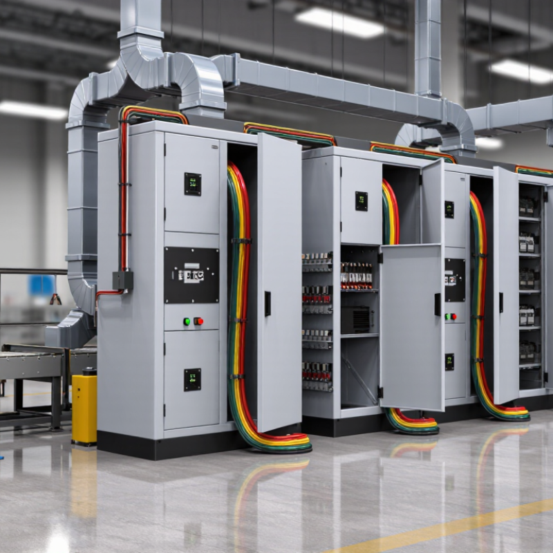
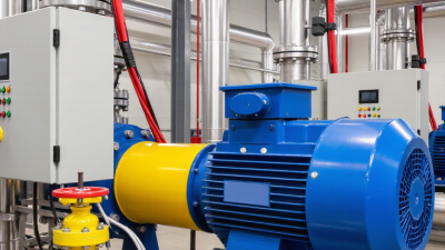
A motor control center (MCC) groups equipment that starts, stops, protects, and monitors electric motors. In a factory, it may stand beside pumps, conveyors, or ventilation systems, with labeled compartments and cables entering from above or below. Each section can contain motor starters, circuit protection, control devices, or feeder equipment. The exact arrangement depends on the installation.
It is more than a cabinet. An MCC helps operators manage multiple motors from one location, while supporting organized maintenance and troubleshooting. A labeled bucket can help a technician identify a circuit quickly; unclear labels can do the opposite. Small details matter. Still, an MCC does not remove electrical hazards, and servicing it requires appropriate training and procedures.
This article explains how motor control centers work and how common types differ. These include traditional fixed designs and withdrawable, or drawout, designs, where compatible units can be removed from their compartments. MCCs may also be described by voltage class, enclosure, or construction standard, so the word “type” can mean different things in different contexts. That distinction is easy to overlook. We’ll look at typical components, compare the main configurations, and outline practical factors such as motor loads, available space, environmental conditions, and maintenance needs. Product specifications and qualified engineering advice should guide selection; a short overview cannot replace either.
What Is a Motor Control Center and What Types Are There?
What a Motor Control Center Is
A motor control center, or MCC, is an assembly that groups equipment for operating and protecting electric motors. It is usually installed in an industrial facility where several motors serve pumps, fans, conveyors, or compressors. Inside a metal enclosure, sections hold motor starters, circuit protection, control components, and shared power busbars. Each motor typically has its own compartment, making equipment easier to identify and service. Some MCCs also include variable frequency drives or programmable controls, depending on the application.
An MCC is more than a row of switches. It brings motor power and control functions together in one organized location. Operators can start or stop motors from local controls, while protective devices help respond to overloads or faults. The exact arrangement varies with motor size, operating conditions, and the facility’s electrical design. A neat drawing can still hide a cramped maintenance space; access needs checking on site.
Main Components of a Motor Control Center
A motor control center (MCC) groups equipment used to start, stop, and protect several motors. Its steel enclosure contains separate sections, often called buckets, for individual motor circuits. Inside each section, components connect to shared power buses. This layout keeps wiring organized and makes routine inspection more manageable. The exact arrangement depends on motor loads and control needs.
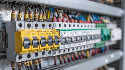
A typical section may include a circuit breaker or fuses for short-circuit protection, a contactor for switching, and an overload relay for responding to excessive motor current. Larger MCCs also have horizontal and vertical bus bars that distribute power between sections. Control transformers can supply lower-voltage control circuits, while relays or programmable controllers handle signals. Variable-frequency drives may be fitted where adjustable motor speed is needed. A grounding bar provides a defined path for fault current.
Small details matter: loose terminals can create heat, even when the enclosure looks clean.
Tips: Check labels against the electrical drawings before servicing. Look for discoloration, dust buildup, and loose connections, but never assume appearance proves safe operation. A tidy panel can still conceal a problem; qualified personnel should verify isolation and inspect components.
How a Motor Control Center Operates
A motor control center operates by routing electrical power from an incoming supply to individual motor circuits. Inside the enclosure, a shared bus carries power to separate compartments, often called buckets. Each bucket contains equipment for one motor or a related process. That may include a circuit breaker, contactor, overload relay, and control components.
When an operator presses a start button, a low-voltage control circuit can energize the contactor coil. The contacts close, allowing power to reach the motor. A stop command opens them again. Simple, but important.
An overload relay monitors motor current and can disconnect the circuit if a sustained overload occurs. Short-circuit protection responds to much larger fault currents. Interlocks may prevent a motor from starting when a guard is open or another process condition is not met.
Some centers use variable-frequency drives to adjust motor speed, while sensors and control systems provide operating signals. The exact arrangement depends on the machinery and the site design. A neat schematic does not always show the full story: loose terminals, heat, or a poorly set overload can change how equipment behaves.
Technicians therefore compare drawings with the installed wiring and check settings before returning equipment to service. Small details matter.
Common Types of Motor Control Centers
Common Types of Motor Control Centers
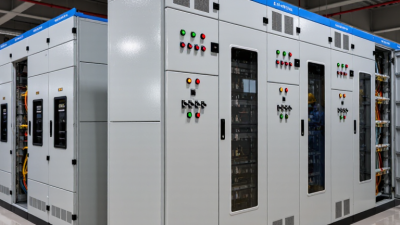
Motor control centers are commonly grouped by voltage, unit construction, and control capability. Low-voltage MCCs serve many plant pumps, fans, and conveyors. Medium-voltage centers suit larger motors and higher-power processes.
Fixed units keep starters bolted in place, while withdrawable units slide out for inspection or replacement. The latter can reduce service disruption, but they require more space and careful interlocking.
Space matters.
Intelligent MCCs add networked relays, sensors, and metering. Operators can review motor current, temperature, and trip history from a control room, though the extra data only helps when someone acts on it.
The U.S. Department of Energy’s 2014 Improving Motor and Drive System Performance sourcebook estimates that motor-driven systems use about 68% of electricity consumed in U.S. manufacturing. That figure explains why starter selection and maintenance deserve attention; it does not mean every motor needs a digital unit.
IEC 61439 provides assembly requirements for low-voltage switchgear and controlgear, while NEMA ICS 18 covers motor control centers. Engineers should check fault ratings, enclosure conditions, feeder layout, and maintenance access.
Classification can overlap: one center may be low-voltage, withdrawable, and intelligent. Not always.
Where Motor Control Centers Are Used
Motor control centers are used wherever several electric motors need coordinated control from one accessible location. In manufacturing plants, they often serve pumps, conveyors, mixers, and compressors along production lines. Operators can monitor equipment status and isolate a motor for maintenance without searching across the building for separate control panels. That can save time. It does not remove the need for safe isolation procedures.
Water and wastewater facilities use motor control centers to operate lift pumps, blowers, screens, and treatment equipment. In commercial buildings, they may control large ventilation fans and central pumping systems. Mines and processing sites also use them for material-handling equipment, where dust, vibration, and long cable runs affect equipment selection. Site conditions matter. A layout that works in a clean utility room may not suit a damp pump station.
In practice, equipment rooms are not always as spacious as drawings suggest. Engineers need to consider access for inspection, heat dissipation, and the center’s electrical ratings before choosing a location. Frequent starts, heavy motor loads, or harsh surroundings can change the required configuration. Even a well-designed center cannot compensate for poor maintenance or unclear operating procedures.