A pump running at full speed can waste electricity when a process needs only half its output. A variable frequency drive adjusts motor speed to match that demand. The difference matters. In ventilation systems, water treatment plants, and production lines, this control can reduce energy consumption and soften mechanical starts. However, savings depend on the load, operating hours, and how the system currently controls flow or pressure.
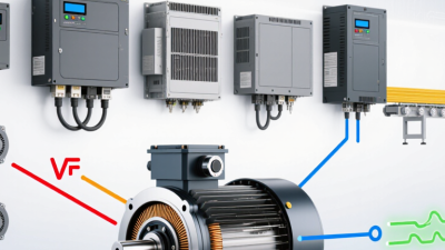
Drives specialist Bill Drury explains in The Control Techniques Drives and Controls Handbook that electronic drives control how electrical energy reaches motors. This principle helps explain how a variable frequency drive works: it changes the frequency and voltage supplied to an AC motor. Inside a typical drive, a rectifier converts incoming AC power into DC. A DC link smooths that supply, while an inverter switches it into a controlled output. For a suitably rated induction motor, reducing frequency generally reduces speed, although actual shaft speed also depends on load and slip.
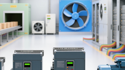
Consider a building’s ventilation fan during a quiet evening, when fewer occupants require less airflow. Instead of maintaining full speed and restricting airflow with dampers, the drive can slow the fan. That sounds straightforward. Installation deserves more thought, however, because motor cooling, cable length, harmonics, and minimum operating speed can affect performance. A drive is not automatically an energy-saving solution for every application. Understanding its components, control methods, and limitations helps you judge where it offers practical value—and where expectations need adjusting.
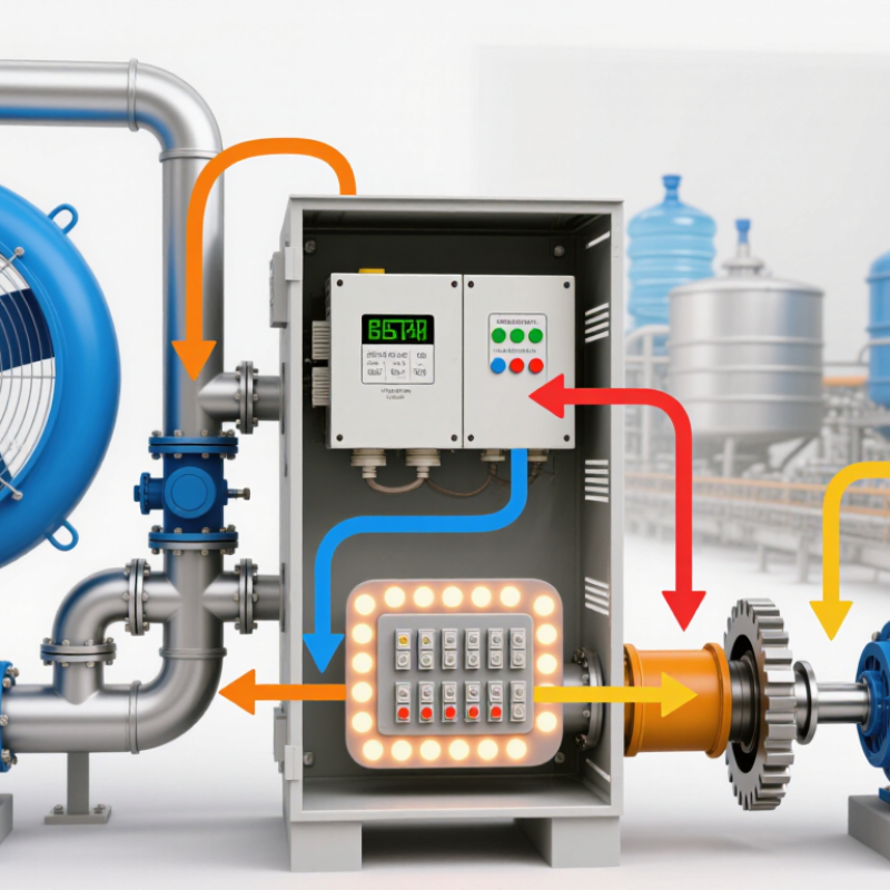
A variable frequency drive (VFD) is an electronic controller that adjusts an AC motor’s speed and torque. It changes the frequency and voltage supplied to the motor. Speed follows demand. Inside, a rectifier converts incoming AC electricity into DC. An inverter then switches that DC into a controlled AC output. You will often find VFDs controlling factory conveyors, ventilation fans, and water pumps. On a packaging conveyor, adjusting motor speed helps match belt movement to the production rate.
The International Energy Agency’s 2011 report, Energy-Efficiency Policy Opportunities for Electric Motor-Driven Systems, estimated motors consumed 43–46% of global electricity. That figure explains why motor control deserves attention, although it does not predict individual savings. For centrifugal pumps and fans, affinity laws indicate that reducing speed by 20% can theoretically reduce power by approximately 49%. Actual results vary. Static pressure, equipment efficiency, and operating hours can substantially change those savings. A VFD running continuously at full speed may offer little energy benefit and introduces conversion losses.
Tips: Record operating hours, motor current, and pressure before selecting a drive. Check the motor’s nameplate voltage and current against the drive ratings. For a pump, confirm minimum flow requirements before lowering speed. One easily missed detail is motor cooling: prolonged low-speed operation can reduce airflow from a shaft-mounted cooling fan.
A variable frequency drive (VFD) controls an AC motor’s speed by adjusting the frequency and voltage supplied to it. Inside a typical drive, three power sections handle this conversion: the rectifier, DC bus, and inverter. Each has a job. The rectifier uses diodes, or controlled semiconductor devices in some designs, to convert incoming AC power into DC. This DC still contains ripple, so it needs conditioning before reaching the motor.
The DC bus forms the middle section, with capacitors that smooth voltage fluctuations and temporarily store electrical energy. Some drives also include a choke to reduce ripple and help manage electrical disturbances. Capacitors retain charge. Even after power is disconnected, technicians must follow the specified discharge time and verify voltage before touching internal components. The inverter then switches semiconductor devices, commonly insulated-gate bipolar transistors, to create a pulse-width-modulated output. These rapid voltage pulses produce motor currents that approximate sine waves, allowing controlled changes in speed and torque.
A control board coordinates switching using programmed settings and measurements such as motor current and bus voltage. Operators enter motor nameplate data, acceleration times, and speed limits through a keypad or external control system. Heat sinks and cooling fans remove heat generated by the power electronics. Their condition matters: dust buildup can restrict airflow and contribute to overheating trips. However, entering nameplate data alone does not guarantee good performance. A heavily loaded conveyor may still need acceleration adjustments or motor tuning, depending on the drive’s capabilities.
A variable frequency drive (VFD) controls an AC motor by adjusting the frequency and voltage supplied to it. Changing the output frequency changes the speed of the motor’s rotating magnetic field, allowing motor operation to match the application’s requirements.
Data basis: synchronous speed is calculated using ns = 120f / P, where f is frequency in hertz and P is the number of motor poles. All values shown use P = 4. These are calculated magnetic-field speeds, not measured shaft speeds. An induction motor’s shaft normally runs slightly below synchronous speed while producing torque because of slip. The frequency range shown is an example; permissible operation depends on motor and drive ratings.
The chart shows the direct relationship between frequency and synchronous speed: doubling the frequency from 30 Hz to 60 Hz doubles the magnetic-field speed from 900 rpm to 1,800 rpm. The VFD coordinates voltage and frequency according to its control method and the motor’s operating limits.
A variable frequency drive, or VFD, controls an AC motor by adjusting its supply frequency and voltage. Inside, power passes through three main stages: a rectifier, a DC bus, and an inverter. The rectifier converts incoming AC into DC, but this voltage still contains ripple. Capacitors smooth it. Some drives also use chokes to reduce ripple or limit current distortion, depending on their design and the demands of the installation.
The inverter uses semiconductor switches to chop DC into voltage pulses. Switching happens rapidly. Through pulse-width modulation, the drive shapes these pulses to produce a controllable fundamental frequency that determines the motor’s rotating magnetic field speed. The output is a pulse train, rather than a smooth sine wave. Motor inductance helps smooth the resulting current.
Motor speed example For a four-pole induction motor, 50 Hz corresponds to a synchronous speed of 1,500 rpm. At 25 Hz, synchronous speed drops to 750 rpm, although actual shaft speed remains slightly lower because torque production requires slip.
Voltage control matters alongside frequency control. Many basic drives maintain an approximately constant voltage-to-frequency ratio below the motor’s rated frequency to support magnetic flux and usable torque. That approach has limits, especially when an application needs strong starting torque or accurate speed regulation at very low operating speeds. Reduced fan cooling can also cause overheating during prolonged low-speed operation. A slower motor is not automatically a cooler motor. Acceleration ramps, cable length, and motor insulation deserve attention during setup.
A variable frequency drive (VFD) controls an AC motor by adjusting the frequency and voltage supplied to it. Inside, a rectifier converts incoming AC power into DC. An inverter then switches that DC into pulses that create controlled AC output. Frequency sets the rotating magnetic field’s speed. For a four-pole induction motor, 60 Hz produces a synchronous speed of 1,800 rpm. At 30 Hz, that becomes 900 rpm. Actual shaft speed runs slightly lower because induction motors need slip to produce torque. Load matters.
Voltage helps maintain the magnetic flux needed for torque. With basic volts-per-hertz control, reducing frequency usually requires a proportional voltage reduction. A motor rated for 460 V at 60 Hz might receive roughly 230 V at 30 Hz. That relationship supports approximately constant torque below base speed, within motor and drive limits. However, low-speed operation may require voltage compensation because winding resistance becomes more significant. Above base speed, voltage usually cannot increase further. Magnetic flux weakens, and available torque falls. There are tradeoffs.
Tips: Check motor current and temperature during a loaded trial, especially at low speeds. A shaft-mounted cooling fan moves less air when the motor slows down. Running a conveyor slowly might look harmless while the motor quietly overheats. A simple volts-per-hertz setting is a useful starting point, but it can struggle with sudden load changes. Vector control can improve torque response, although accurate motor settings still matter.
A variable frequency drive (VFD) controls an AC motor by adjusting the frequency and voltage supplied to it. A typical AC-input VFD rectifies incoming AC into DC, smooths it in a DC link, and uses an inverter to produce a pulse-width-modulated output with a controllable fundamental frequency and voltage.
| Output Frequency | Fundamental Output Voltage | Voltage / Frequency | Synchronous Speed | Approximate Flux Relative to Base | Ideal Torque Capability | Ideal Power Capability | Operating Region |
|---|---|---|---|---|---|---|---|
| 20 Hz | 160 V | 8.00 V/Hz | 600 rpm | 100% | 100% | 40% | Below base speed: constant V/Hz and approximately constant torque capability. |
| 25 Hz | 200 V | 8.00 V/Hz | 750 rpm | 100% | 100% | 50% | Half the base frequency produces half the synchronous speed. |
| 40 Hz | 320 V | 8.00 V/Hz | 1,200 rpm | 100% | 100% | 80% | Voltage rises with frequency to maintain approximately constant magnetic flux. |
| 50 Hz | 400 V | 8.00 V/Hz | 1,500 rpm | 100% | 100% | 100% | Base operating point: the assumed motor voltage and frequency ratings. |
| 60 Hz | 400 V | 6.67 V/Hz | 1,800 rpm | 83.3% | 83.3% | 100% | Above base speed: voltage is limited, flux weakens, and available torque decreases. |
| 75 Hz | 400 V | 5.33 V/Hz | 2,250 rpm | 66.7% | 66.7% | 100% | Ideal constant-power operation, provided motor and drive limits permit it. |
An induction motor's shaft runs below synchronous speed while producing motoring torque; the difference is called slip. Actual torque depends on load, current, flux, and control method. The table describes available capability rather than torque automatically delivered to the load.
At low frequencies, stator resistance makes a simple constant V/Hz relationship less accurate, so voltage compensation or vector control may be needed. Reduced cooling can also limit continuous torque when the motor uses a shaft-mounted fan. Above base frequency, current limits, breakdown torque, mechanical speed limits, and load requirements can reduce the usable constant-power range. Output voltage values refer to the fundamental line-to-line RMS component of the PWM waveform.
A variable frequency drive (VFD) controls an AC motor’s speed by adjusting the frequency and voltage supplied to it. It typically converts incoming AC power to DC, then uses electronic switches to create a controlled AC output. Common applications include ventilation fans, water pumps, conveyors, and industrial mixers.
Consider a building’s ventilation fan running at full speed while dampers restrict airflow. A VFD can reduce fan speed to match demand, cutting wasted energy and often reducing noise. Demand matters.
The largest energy savings often occur in centrifugal pumps and fans operating below full capacity.
Under ideal conditions, reducing speed by 20% can cut their required shaft power by roughly 49%.
Actual electrical savings depend on system pressure, equipment efficiency, and operating hours. That estimate deserves scrutiny. A pump lifting water against substantial static head may deliver much smaller savings.
Controlled acceleration also reduces abrupt mechanical loads on belts, couplings, and connected equipment. For conveyors, adjustable speed helps operators coordinate material flow between production stages.
VFDs introduce costs and technical constraints that deserve attention before installation. Their switching can contribute to motor insulation stress, bearing currents, and electrical interference, particularly with long motor cables.
Selection should account for motor compatibility, load torque, enclosure conditions, and the lowest required operating speed.